
It’s the age old question. A question that has been boggling mankind for decades.
Why do floppy ribbon cables contain a twist? I’ve wondered this from the moment I first opened my PC to reveal it’s glorious contents. It looks like a hack. Something wasn’t quite right in the design, but was fixed by reversing a few wires. And this is essentially, accurate.
Modern systems generally lack our beloved A: drive. That magical slot which brought such a wide variety of sound and volatility to proceedings, but go back a couple of decades and these devices were completely essential. During the 1990s they were commonly connected directly to the motherboard, much like your hard drive, and with a cable very much reminiscent to your hard drive’s IDE connection, however whereas an IDE cable has 40 wires, the floppy cable only has 34.
Much like an IDE cable, a floppy ribbon usually has multiple connectors. For IDE these were used to connect up to 2 drives which could then be denoted as a slave drive, or a master drive, allowing 2 hard drives or a hard drive and CD drives to be linked to a single IDE channel.
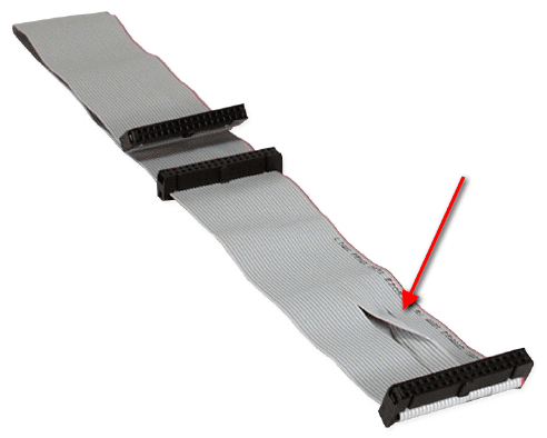
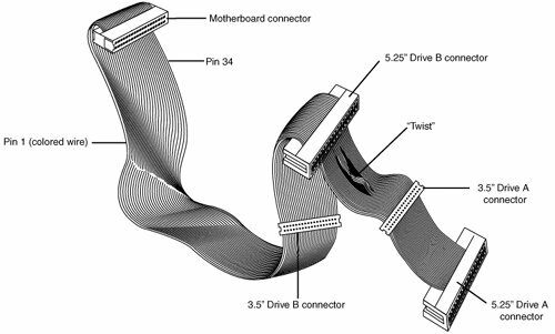
Traditional floppy cables would have 5 connections. One to attach to the motherboard, with 2 for the A: drive, depending on whether it’s a 5 1/4″ drive – which use card edge connections, or a 3.5″ – which use pin header connections, and 2 for the B: drive. In later systems the 5 1/4″ connectors were negated, as was sometimes the B: drive connection, meaning a cable could just have the drive and motherboard connector.
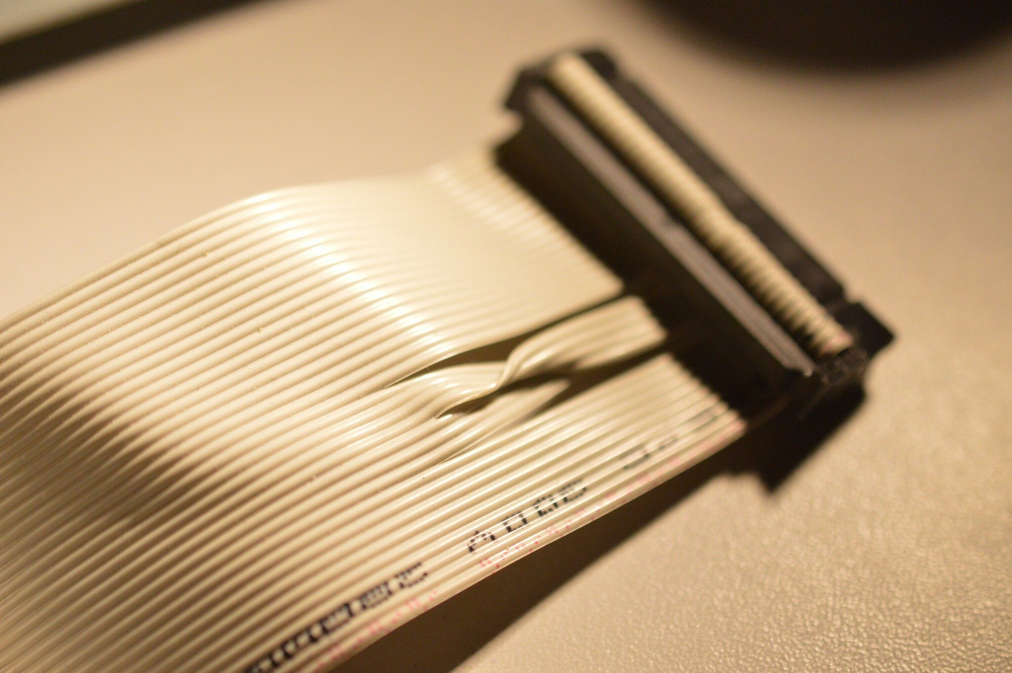
So that’s all good and dandy, but what about this little twist?
To answer this we have to go back to the birth of floppy drives – in an IBM PC sense at least, and as usual we begin with the IBM 5150.
Back then floppy drives relied on a drive select jumper to determine which drive as A: and which drive was B:. These jumpers required setting, even if there was only 1 floppy unit in the system. With 2 drives installed, this was essential so that the single floppy header could determine which drive it was talking to on the single cable.
If you wanted to install a new drive in your single drive system, then you’d have to make sure the jumpers were set correctly on each drive so the system could differentiate between them. Likewise, if you wanted to remove a floppy, you’d have to remove the one setup as the B: drive, or swap the jumper settings over. This doesn’t sound like much of a chore, but IBM realised that it was a pain swapping jumpers around when dealing with mainframes. Their solution for this was to setup every floppy drive to be a B: drive as standard and instead rely on the cable to determine which is which.
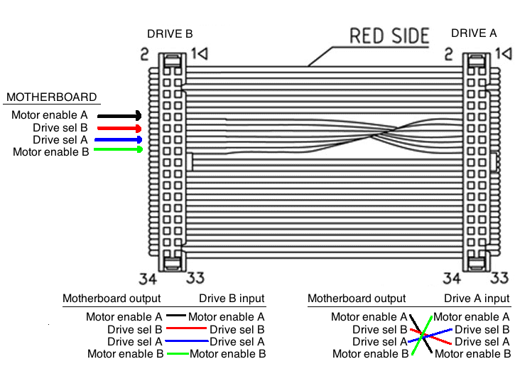
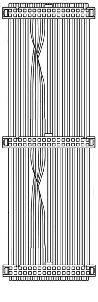
The twisted wire numbers 10 to 16. Wires 11,13 and 15 are ground wires which carry no signals, however wire 10 and 16 are the motor enable wires for drives A and B respectively, whilst 12 and 14 are drive select B and A respectively. Therefore, by inverting these wires, any drive after the twist automatically becomes the A: drive and the drive before the twist remains as a B: drive. So rather than messing around with jumpers, you simply plugged the last connector into the floppy you wanted as A: and the other connector would plug into B:. The other wires carrying the data and head select routines would then only apply to which drive was selected by the floppy controller, as an unselected drive simply ignores the input.
For a while some systems actually retained the jumper approach or even actually tried to use their own hack, such as twisting the signals on the motherboard rather than the cable, but this just caused confusion, especially when a twisted cable was used, and the IBM standard was eventually adopted by everyone.
It’s quite a simple hack, which although gives the ribbon cable an “after-thought” appearance, works beautifully and saves us from losing all those plastic jumper connectors under our desks for the rest of eternity.
So what about our IDE cables and hard drives? Well, there was actually a cable select protocol which used the exact same idea. To use it, both devices needed to be setup for “cable select”, ironically through the use of a jumper, and then through use of a specific cable, wire 28 is only connected to the master drive. This means that in this instance, the master drive needs to be the middle connector and the slave the end connector, the opposite of our floppy setup. This inconsistent implementation was one reason it never really caught on, unlike our simple, but beloved floppy cable twist.
Strangely there was also a cable which did the twist before the first connector, and then twisted again for the second drive, requiring drive A: to be placed in the middle connector. This appears to be to meet a particular case design, because other than that, it’s rather bizarre to say the least.

Nostalgia Nerd is also known by the name Peter Leigh. They routinely make YouTube videos and then publish the scripts to those videos here. You can follow Nostalgia Nerd using the social links below.


2 Comments
Add Yours →Thanks for sharing 🙂
do u know anything about 2.88mb floppies? have u scene the mb-02+ hi density disk interface with dma for the zx spectrum?